Wednesday, May 23, 2007

SQL trick for flattening a parent-child table and vice versa

Among other things this blog is about saving tricks for future use. This SQL trick I used in my previous example of hierarchical organization structure = How to flatten a parent-child table.

Suppose you have the following parent-child table for your hierarchy:

CREATE TABLE hierarchy_parent_child (
node_id INTEGER NOT NULL,
parent_id INTEGER,
node_name VARCHAR(40)
);


.. and the table contains data like this (please note NULL in root parent_id):
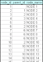


.. and you want to change it into flat format, here's the SQL:

SELECT
lev01.node_id id_01, lev01.node_name name_01,
lev02.node_id id_02, lev02.node_name name_02,
lev03.node_id id_03, lev03.node_name name_03,
lev04.node_id id_04, lev04.node_name name_04,
lev05.node_id id_05, lev05.node_name name_05,
lev06.node_id id_06, lev06.node_name name_06,
lev07.node_id id_07, lev07.node_name name_07,
lev08.node_id id_08, lev08.node_name name_08,
lev09.node_id id_09, lev09.node_name name_09,
lev10.node_id id_10, lev10.node_name name_10
FROM hierarchy_parent_child lev01
LEFT OUTER JOIN hierarchy_parent_child lev02 ON lev01.node_id = lev02.parent_id
LEFT OUTER JOIN hierarchy_parent_child lev03 ON lev02.node_id = lev03.parent_id
LEFT OUTER JOIN hierarchy_parent_child lev04 ON lev03.node_id = lev04.parent_id
LEFT OUTER JOIN hierarchy_parent_child lev05 ON lev04.node_id = lev05.parent_id
LEFT OUTER JOIN hierarchy_parent_child lev06 ON lev05.node_id = lev06.parent_id
LEFT OUTER JOIN hierarchy_parent_child lev07 ON lev06.node_id = lev07.parent_id
LEFT OUTER JOIN hierarchy_parent_child lev08 ON lev07.node_id = lev08.parent_id
LEFT OUTER JOIN hierarchy_parent_child lev09 ON lev08.node_id = lev09.parent_id
LEFT OUTER JOIN hierarchy_parent_child lev10 ON lev09.node_id = lev10.parent_id
WHERE lev01.parent_id IS NULL;


.. then it returns rows like this:


The example above works for ten levels but it's easy to add more levels by repeating the pattern.

If you want to go vice versa, suppose you have the following flat hierarchy table:

CREATE TABLE hierarchy_flat (
id_01 INTEGER,
name_01 VARCHAR(40),
id_02 INTEGER,
name_02 VARCHAR(40),
id_03 INTEGER,
name_03 VARCHAR(40),
id_04 INTEGER,
name_04 VARCHAR(40),
id_05 INTEGER,
name_05 VARCHAR(40),
id_06 INTEGER,
name_06 VARCHAR(40),
id_07 INTEGER,
name_07 VARCHAR(40),
id_08 INTEGER,
name_08 VARCHAR(40),
id_09 INTEGER,
name_09 VARCHAR(40),
id_10 INTEGER,
name_19 VARCHAR(40)

);

.. then you can do SQL like this:

SELECT DISTINCT id_01 node_id, NULL parent_id, name_01 node_name
FROM hierarchy_flat
UNION
SELECT DISTINCT id_02 node_id, id_01 parent_id, name_02 node_name
FROM hierarchy_flat WHERE id_02 IS NOT NULL
UNION
SELECT DISTINCT id_03 node_id, id_02 parent_id, name_03 node_name
FROM hierarchy_flat WHERE id_03 IS NOT NULL
UNION
SELECT DISTINCT id_04 node_id, id_03 parent_id, name_04 node_name
FROM hierarchy_flat WHERE id_04 IS NOT NULL
UNION
SELECT DISTINCT id_05 node_id, id_04 parent_id, name_05 node_name
FROM hierarchy_flat WHERE id_05 IS NOT NULL
UNION
SELECT DISTINCT id_06 node_id, id_05 parent_id, name_06 node_name
FROM hierarchy_flat WHERE id_06 IS NOT NULL
UNION
SELECT DISTINCT id_07 node_id, id_06 parent_id, name_07 node_name
FROM hierarchy_flat WHERE id_07 IS NOT NULL
UNION
SELECT DISTINCT id_08 node_id, id_07 parent_id, name_08 node_name
FROM hierarchy_flat WHERE id_08 IS NOT NULL
UNION
SELECT DISTINCT id_09 node_id, id_08 parent_id, name_09 node_name
FROM hierarchy_flat WHERE id_09 IS NOT NULL

UNION
SELECT DISTINCT id_10 node_id, id_09 parent_id, name_10 node_name
FROM hierarchy_flat WHERE id_10 IS NOT NULL

ORDER BY 1

.. and you get the original parent-child table.

Again, repeat the pattern to enable more than ten levels.

Tuesday, May 22, 2007

XY chart and hierarchical graphs

Here's a video that continues the XY chart ideas in my previous postings. (Sorry for really bad blurring. Anyway, as crappy as this video is, you can see the idea.)


This sample hierarchical system (hierarchical graph) consists of 25 thousand parts in maximum eight levels. It allows me to drill-down from any branch (only one branch is open at each level). When I return to an upper level, all lower levels and nodes under it disappear and new branching starts.

Here's a better image:


This graph user interface is contextual. It's the only practical way to display large graphs in a limited space such as on a computer screen. It only shows the related nodes around the selected one. Following this principle, in a non-hierarchical graph you can display nodes linked to the central node, as well as the nodes linked to them (1st and 2nd level links). When you click a node, the clicked node becomes the central one, etc.

This kind of user interface is good for exploring large organization structures (or any hierarchical graphs). Since the system relies on the idea of drilling-down (actually, self-drilling), it's well possible to display extra information (tables and charts) about the currently selected node near the hierarchy tree (under it or to the right of it).

Technically, to calculate (x, y) coordinates, each hierarchy node has to know its level, the max number of levels, the order within its siblings (between 1...n), and the number of siblings (n).

x = my sibling id / number of siblings - 1 / (2 * number of siblings)
y = 1 - (my level / max number of levels)

The lines between nodes are drawn with the same kind of principles as in my previous postings.

Wednesday, May 16, 2007

Accidental chart art

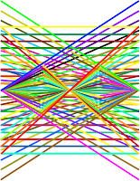
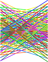
Sometimes you end up creating beauty by accident. (They are line charts.)

Sunday, May 13, 2007

XY chart and graph theory

Do you know graph theory? To me it's inspiring as such. In business intelligence, a graph (in the meaning of graph theory) provides a method to visualize relationships between entities such as between people, companies, geographical locations, etc.


Hierarchical systems, where each element of the system (except for the top element) is subordinate to a single other element, are graphs too. Various organization charts and genealogy charts (both in biology and as family trees) are good examples of such graphs.

XY chart is a good way to visualize graphs. To do it clearly, at least XY must be able to:


  • Draw data points (entities)
  • Draw lines between data points to visualize existing relationships
  • Label data points (entities)
In my previous posting I already wrote about the first two aspects. The third aspect, labeling a data point, is necessary to understand the meaning of nodes of a graph.

The following step-by-step example shows a method how you can automatically create a graph by using XY and two tables graph_node (entities) and graph_link (relationships).

1. Create the graph_node and graph_link tables.

CREATE TABLE graph_node (node_id VARCHAR(3), node_name VARCHAR(40), node_order INTEGER, node_count INTEGER);
CREATE TABLE graph_link (node1_id VARCHAR(3), node2_id VARCHAR(3));

2. Populate tables with countries of Europe and border neighboring relationships (or anything you wish).


Note that I have included the node_order and node_count columns in the graph_node table. They are necessary to calculate (x, y) locations of data points later on. In a real situation, you should calculate node_order and node_count automatically by using SQL (or perhaps your OLAP system is able to calculate them on the fly).

By the way, there are 43 countries in Europe and 80 borders between them (not including Vatican and Turkey as nodes; including RUS-LTU, RUS-POL, and GBR-ESP relationships because of separate areas of Kaliningrad and Gibraltar).

3. Create a graph_link_view based on the two tables:

CREATE VIEW graph_link_view (link_id, datapoint_id, node_id)
AS
SELECT CONCAT(node1_id,node2_id), 0, node1_id FROM graph_link
UNION
SELECT CONCAT(node1_id,node2_id), 1, node2_id FROM graph_link
UNION
SELECT CONCAT(node1_id,node2_id), -1, NULL FROM graph_link
UNION
SELECT node_id, 0, node_id FROM graph_node
WHERE node_id not in (select node1_id from graph_link)
AND node_id not in (select node2_id from graph_link)
UNION
SELECT node_id, -1, NULL FROM graph_node
WHERE node_id not in (select node1_id from graph_link)
AND node_id not in (select node2_id from graph_link);

This view is necessary because of the way the XY chart draws data points and lines between them (see my previous posting). The following image shows some contents of the view:


Each row in graph_link table produces 3 rows in graph_link_view with datapoint_id values -1, 0, and 1 (0=start line, 1=finish line, -1=break line). Some nodes such as Iceland does not have border relationships with other country nodes, so it produces 2 rows into view (-1, 0).

4. Use the following query behind your report.

SELECT link.link_id, link.datapoint_id, node.node_id, node.node_name, node.node_order, node.node_count
FROM graph_link_view link
LEFT OUTER JOIN graph_node node ON link.node_id = node.node_id;

5. Create the measure dimension with the followin three calculations:

X = MIN(SIN(360*node.node_order/node.node_count/180*PI()))
Y = MIN(COS(360*node.node_order/node.node_count/180*PI()))
Label = MIN(node.node_id)

6. Create other dimensions as follows:

Outer category = link.link_id
Middle category = link.datapoint_id
Inner category = node.node_name (=serves as a tool tip label)

7. Create an XY chart and format it as follows:


The XY chart displays countries as data points in circle and border neighboring relationships between them as lines. Iceland and Malta aren't connected (they are islands).

A few notes:

I created this XY chart with the Voyant tool. It displays the data point label to the right of the data point. Additionally, when you move the mouse cursor over a data point, I specified the chart to display the inner category dimension as a tool tip (ISL data point displays "Iceland").

I explored some other OLAP charting tools whether or not it's possible to create the same XY. All of them seem to fall short in displaying data point labels, such as Excel, BusinessObjects Desktop Intelligence and Web Intelligence. Why such a useful feature is not supported by them, I don't know?

About the XY chart itself, it's actually somewhat hard to read, because the lines cross so often. Therefore I created another chart (below) in which I used longitudes and latitudes for (x, y) coordinates. Much better!


And of course, there's no meaning in displaying neighbor country relationships as a graph, because a simple map of Europe will do.

Nevertheless, the method above is ok to visualize connections found within customer relationship databases. For example, supposing your CRM database contains information about meetings (when, who, on which project), you can use this data to visualize which people were involved together in certain projects at certain time period. An XY graph visualizes this much better than a table.

I will now put an end to this posting, though I have two more issues in my mind:


  • What to do if your graph is very large?
  • Hierarchical graphs?
Later...

UPDATE (May 14, 2007): I've forgotten two borders, one between Germany and Czech Republic and another between Switzerland and Austria.

UPDATE (May 18, 2007): I recently learned that there's software for fully automated graph layout, Mathematica 6. If this functionality existed in some OLAP tool, it would be nice.

Wednesday, May 9, 2007

XY chart and a regular polygon example

XY chart (scatter chart) is one of my favourites, because it allows you to plot your data more freely. I already used XY in the posting about Crystal Xcelsius. In this posting I will document one interesting method available in most standard OLAP tools. See the following video.


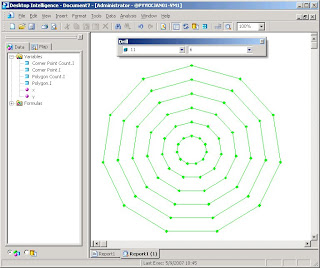
In the video, I use the first menu choice/filter to change the number of sides in a regular polygon. The second menu choice/filter allows me to decide the number of nested polygons drawn within each other.

I used the Voyant OLAP tool in the video. Can you do it too? Probably you can!

In this posting, I assume that your OLAP XY chart is capable of plotting both symbols and lines between symbols. I also assume that if some (x, y) coordinate is missing in between, then the line breaks, such as in the following sample XY chart in Excel.


Step-by-step:

1. Create a database table:

CREATE TABLE integers (i INTEGER, one INTEGER)

2. Populate the integers table with 32 rows: the i column contains numbers between -1 and 30; the one column has NULL for -1 and 1 for other numbers.

INSERT INTO integers VALUES (-1, NULL);
INSERT INTO integers VALUES (0, 1);
INSERT INTO integers VALUES (1, 1);
INSERT INTO integers VALUES (2, 1);
...
INSERT INTO integers VALUES (29, 1);
INSERT INTO integers VALUES (30, 1);

3. Create the following query behind your report:

SELECT corner_point.i, corner_point.one, corner_point_count.i, polygon.i, polygon_count.i
FROM
integers corner_point,
integers corner_point_count,
integers polygon,
integers polygon_count
WHERE corner_point.i <= corner_point_count.i

AND corner_point_count.i BETWEEN 3 AND 30
AND polygon.i <= polygon_count.i
AND polygon.i >= 1
AND polygon_count.i BETWEEN 1 AND 12;

The integers table is used in four different meanings: individual corner point, number of corner points (between 3 and 30), individual polygon, number of nested polygons (between 1 and 12).

Note that in the query, each regular polygon with n corners has n+2 corner points (-1, 0, 1, 2, 3, ..., n). One extra corner point is necessary for drawing a closed polygon. The -1 corner point is necessary to break a line before starting to draw an inner polygon (NULL corner point).

By the way, the query returns 40404 rows. Can you calculate why?

4. Create a report by using the following calculations for coordinates:

x = MIN(polygon.i/polygon_count.i*SIN(360*corner_point.i/corner_point_count.i/180*PI()*corner_point.one))
y = MIN(polygon.i/polygon_count.i*COS(360*corner_point.i/corner_point_count.i/180*PI()*corner_point.one))

Note that both calculations have *corner_point.one multiplication in it to cause the (x, y) coordinate for -1 to change into (NULL, NULL).

5. Create other dimensions as follows:

Menu 1 = corner_point_count.i
Menu 2 = polygon_count.i
Outer category = polygon.i
Inner category = corner_point.i

6. Build the report and change the chart type into XY.


7. Change into manual scale by using limits -1 and +1 for both axes. Hide the legend, axes, and unnecessary gridlines. Change all symbols to have the same color.


The report is ready!

I also tried other OLAP tools. BusinessObjects Desktop Intelligence performed well:


I tried BusinessObjects Web Intelligence / InfoView. Unfortunately the last step failed, because I wasn't able to draw lines between data points.

Then I tried Microsoft SQL Server 2000 Analysis Services, but without success. There was a couple of reasons such as: the cube editor only allows equijoins between tables while my query needs <= operators; PivotTable in Excel is not able to utilize XY chart. Has the situation changed in the 2005 Analysis Services? I don't know.

That's all for this time. Though this nested polygon example is not useful in business intelligence as such, it documents a method how you can use an XY chart to draw something new. In the following postings, I'll continue this idea and show something that is indeed very useful!

Wednesday, May 2, 2007

Self-drilling and problem solving expert system--easy job!

I continue the topic of self-drilling introduced in my previous posting. Is the following flowchart familiar to you?


It's actually a finite state machine that represents a simple expert system driven by questions and aswers. In the database you can model the flowchart by using two tables: exp_state and exp_transition.


By using self-drilling reports and Voyant, I created an expert system OLAP model. See the following video:


It was quite easy. My solution is general. If you'd put thousands of questions and answers in the exp_state and exp_transition tables, it would work as perfectly as in the video. (There's no limit on the number of optional answers per question or the length of questions and answers.)

I call this a simple expert system, because a true expert system should allow fuzzy logic (probabilities between 0 and 1), which this system does not do. Also a true expert system should be able to calculate costs (or something else) based on the choices made by the user.